When λ/4 Is Affordable and λ/10 Blows Your Budget: Why Antenna Physics Makes IoT Projects More Expensive Than Expected
Boards get smaller, but physics doesn’t. Anyone trying to fit an integrated LTE-M or 5G antenna into a tight space at 690 MHz will eventually hit the Chu-Harrington limit – and that’s when development gets very expensive fast. A guest post by Harald Naumann on the laws of nature that blow engineering budgets.
Key Takeaways
- The Chu-Harrington theorem sets hard physical limits for electrically small antennas: the smaller the device, the narrower the bandwidth and the higher the losses – with exponentially growing development effort.
- Development costs for integrated LTE-M/5G antennas do not scale linearly but exponentially as board size shrinks – from around €3,000 at optimal size (λ/4) to over €120,000 for heavily miniaturized designs (λ/10).
- Minor geometry changes can dramatically reduce effort: in one real wearable project, adding just 10 mm to the PCB length cut estimated development costs by around €70,000.
The Problem: Smaller Isn’t Always Cheaper
In electronics development, a common rule of thumb holds that smaller boards mean less material, less weight, lower costs. For processors, memory, and sensors, that’s largely true today. For antennas, it isn’t – at least not without serious caveats.
Anyone developing an integrated LTE-M or 5G antenna for the 690 MHz frequency range is working with a wavelength of around 434 mm. The ideal antenna length, known as a quarter-wave or λ/4, sits at approximately 108.5 mm. For many modern IoT devices – especially wearables or compact sensor nodes – that’s simply too long. So the antenna gets shorter. And that’s where the real trouble begins.
The Chu-Harrington Theorem: Physics as a Hard Limit
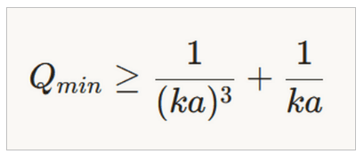
The Chu-Harrington theorem, named after engineers Leonidas Chu and Roger Harrington, describes a fundamental physical limit for electrically small antennas – that is, antennas significantly smaller than the wavelength of the signal they are meant to radiate.
The decisive parameter is the Q-factor (quality factor), which measures how narrowband an antenna operates. Put simply: the smaller the electrical volume of an antenna relative to the wavelength, the larger the minimum Q-factor must be. In practice, this means more reactive components in the circuit, reduced usable bandwidth, and increasing signal losses.
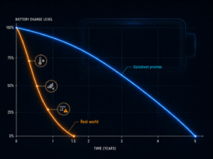
At ka<1, Qmin rises drastically
One thing is important to grasp: the Q-factor does not grow linearly but on a logarithmic scale – what appears manageable at a modest size reduction becomes rapidly uncontrollable with further miniaturization.
The theorem is no academic edge case. It describes the physical reality that every antenna engineer faces the moment they try to go below a certain form factor.
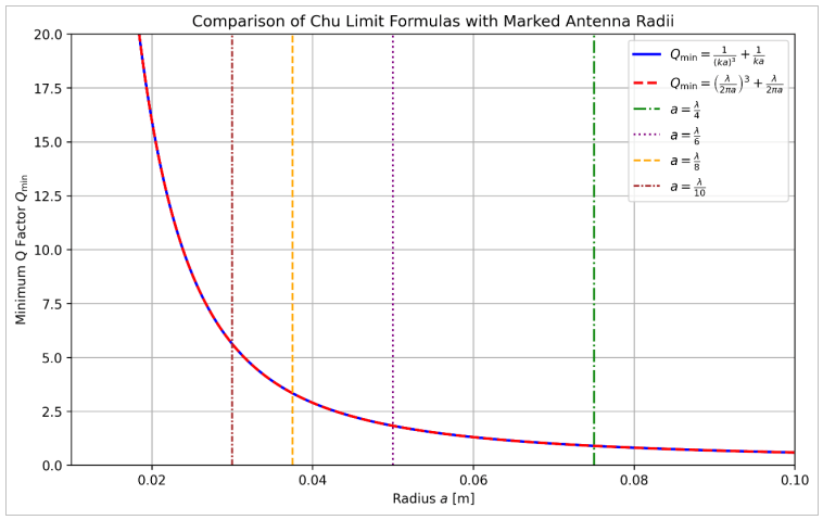
Note: The Qmin graph uses a logarithmic scale.
The Cost Curve: Exponential, Not Linear
From practical experience, development effort for integrated LTE-M/5G antennas at 690 MHz can be described empirically. The following formula captures how costs behave as a function of groundplane length L – that is, the usable PCB area available for the antenna:
Cost(L) = 3,080 / (L / 108.5)⁴ − 64 | f = 690 MHz | λ/4 = 108.5 mm
The reference value of 108.5 mm corresponds to the quarter-wave at 690 MHz. The fourth power in the formula is no coincidence – it directly mirrors what the Chu-Harrington theorem predicts theoretically.
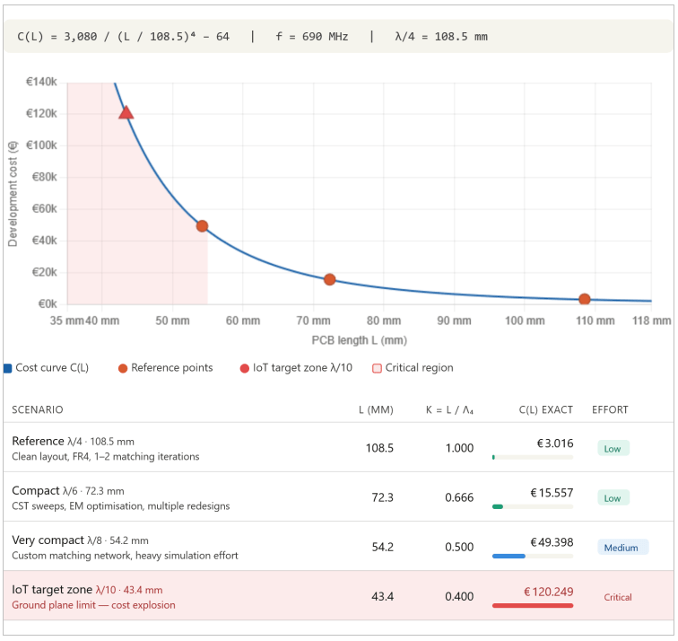
Behind these costs are not arbitrary markups but real engineering effort: frequency-critical impedance matching networks with tight component tolerances, multiple simulation cycles, measurements in an anechoic antenna chamber, and demanding qualification procedures. The smaller the antenna, the more sensitive the system becomes to the tiniest layout changes – and the more iterations are required.
Real-World Example: 10 mm Difference, €70,000 Saved
A concrete development project illustrates the issue particularly clearly. The request was for an LTE-M antenna for a wearable device at 690 MHz, integrated on a PCB measuring 40 × 20 mm². Electrically, that corresponds to roughly λ/10 – the lowest range in the table above.
Impedance matching proved highly complex: multiple reactive stages and components with very tight tolerances were required. The estimated development cost: over €120,000, with limited reproducibility in subsequent production.
The solution was surprisingly straightforward. The PCB size was increased to 50 × 20 mm² – just 10 mm more in length. That puts it at approximately λ/8. The result: the Q-factor dropped by around 50%, the usable bandwidth doubled accordingly, and achieving adequate matching (VSWR < 2:1, a measure of how efficiently a signal is transferred between transmitter and antenna) was projected to require just two reactive stages instead of significantly more. Development costs fell to under €50,000 – with considerably higher manufacturing stability.
Counterstrategy: Adaptive Matching Instead of Rigid Design
Beyond the obvious fix of planning for more space, another approach has established itself in practice: adaptive RF circuits that actively compensate for the shrinking frequency window of small antennas.
One example is the use of the MIPI-RFFE bus (Radio Frequency Front-End, an interface standard developed by the smartphone industry for RF components) in combination with programmable RF switches. One switch handles center frequency adjustment to accommodate the narrowing bandwidth – in up to 15 steps – while a second compensates for impedance drift, which refers to fluctuations in the antenna’s resistive behavior that become especially significant in small designs.
The advantage of this approach: it shifts part of the matching work from static circuit design into software, making the design more robust against manufacturing tolerances. The Chu-Harrington limit is not lifted by this, but its practical consequences become more manageable.
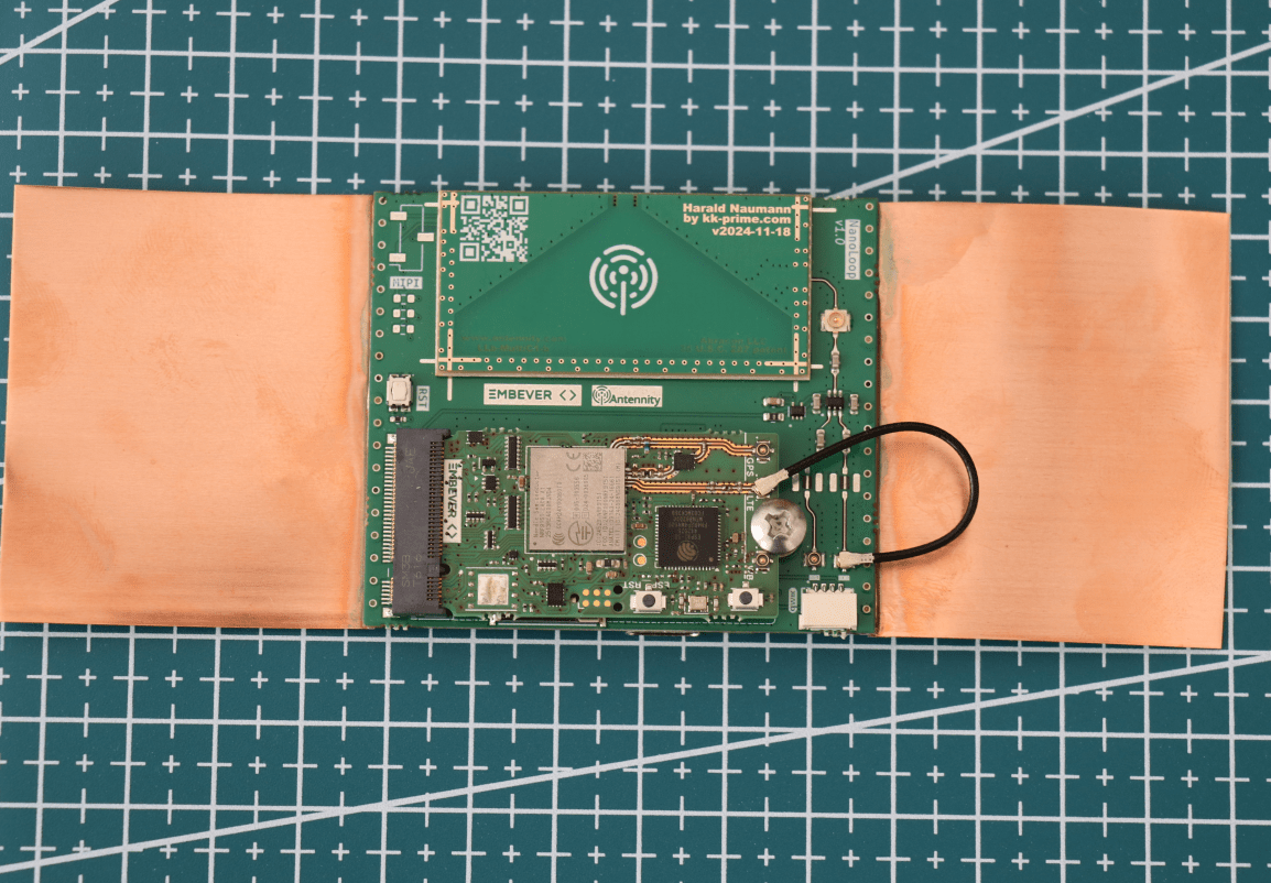
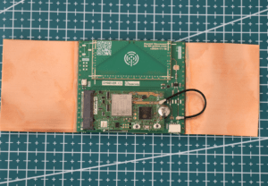
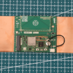
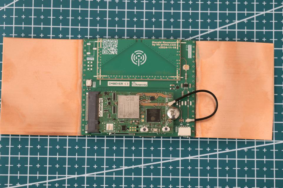
NanoLoop PCB with M.2 card and nRF9151 and “Virtual Plane” via copper foil by Antennity.
What Developers and Product Managers Should Take Away
The Chu-Harrington limit is not an obstacle that better software or more experienced engineers can overcome. It is a physical reality. Several practical conclusions follow from this.
Board size is a cost parameter – a massive one. Anyone who locks in housing dimensions before antenna design has been considered risks six-figure surprises later in the process.
Antenna design belongs in the early product phase. At the latest when form factor and target frequency are defined, an antenna engineer should be involved – not after boards have already been manufactured.
Small geometry changes can have large effects. The practical example shows: 10 mm more in length can mean the difference between a manageable project and one that is prohibitively expensive.
And finally: the theorem applies universally. Whether LTE-M, NB-IoT, 5G NTN, or another radio technology – as soon as the antenna becomes electrically small (ka < 1, where k is the wave number and a is the radius of the smallest enclosing sphere around the antenna), the described laws apply.
Conclusion: Physics Is Not a Negotiating Partner
IoT device miniaturization has made enormous strides in recent years. Chips get smaller, more power-efficient, and more capable. The antenna, however, follows different rules – it is bound to the wavelength of the signal it must radiate, and that wavelength cannot be shortened by better semiconductor processes.
The Chu-Harrington theorem makes this limit quantifiable. Anyone who knows it and factors it into product decisions early can avoid costly detours. Anyone who ignores it pays – potentially with six-figure rework costs and delayed market entry.